Project Context项目背景 / 02
High-speed Dual-chamber Component Installation Machine高速双腔组件安装机
This project covers the adapter-handling subsystem: transfer, three heating stages, insertion and rejection. The mechanical design combines a six-station rotary table with a below-platform drive, vertical positioning and pneumatic insertion.本项目聚焦适配器转运、三段加热、安装与剔废子系统。机械方案采用六工位转盘,配合台面下方的传动、升降定位及气动推装机构。
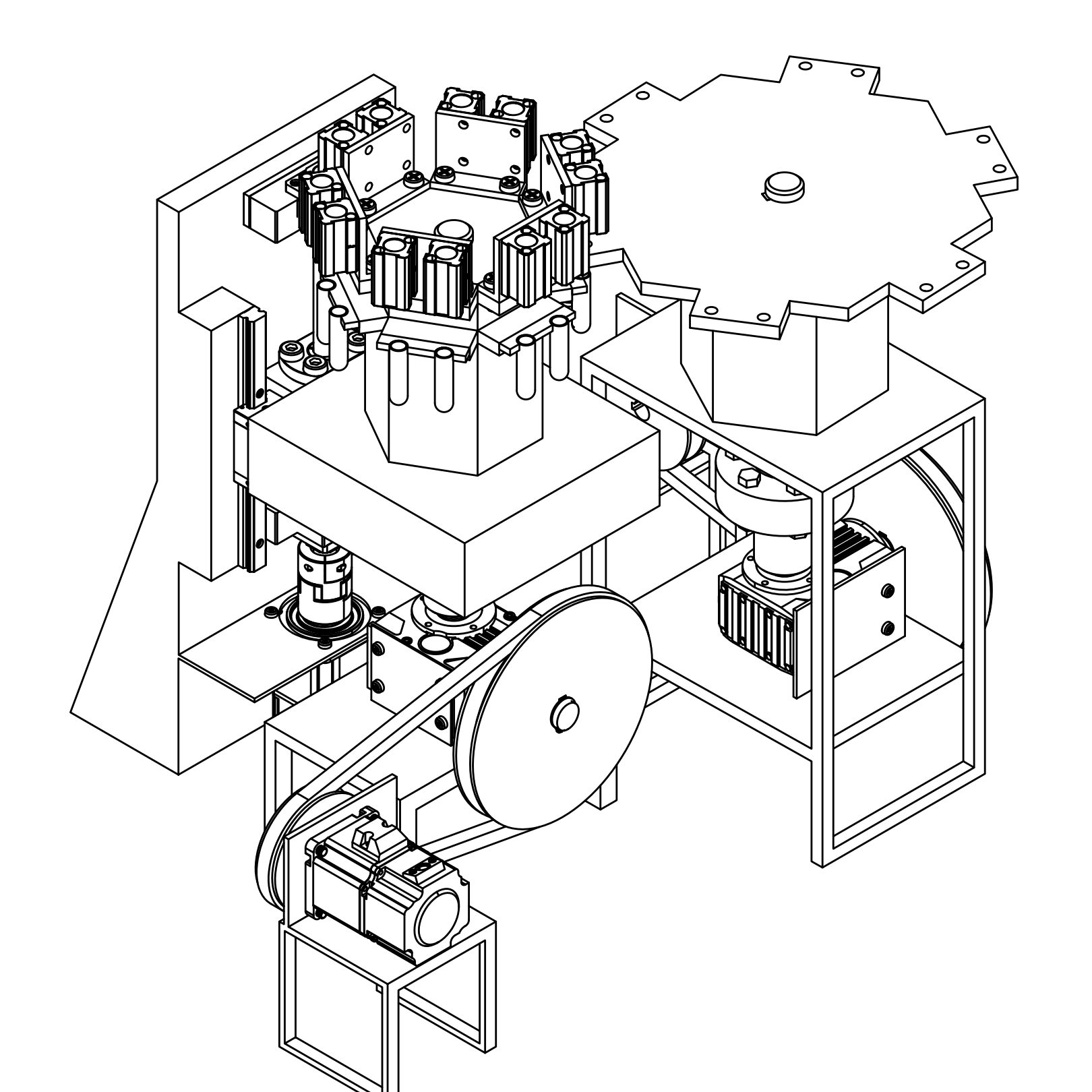
Processed isometric drawing of the material-transfer subsystem, showing its rotary tables and drive components. It depicts this subsystem only, not the complete machine.物料转运子系统的处理后轴测图,展示其转盘及驱动部件。图中仅为该子系统,并非整机。
I designed the complete machine independently, working out its structure, transmission, calculations and component selection.整机机械设计由我独立完成,包括结构、传动、计算与零部件选型。
Drawings and models from company and client projects are processed versions, adapted to protect confidentiality. Academic design materials are my own original work. Conceptual models and simulations are preliminary studies, not validated results.公司与客户项目的图纸和模型均为经过处理的版本,以保护保密信息;学术设计资料为本人原创;概念模型与仿真为初步研究,并非经验证的结果。
View 3D assembly ↓查看三维装配 ↓Designed for Aseptic Biopharmaceutical Applications符合生物制药无菌性要求
As a biopharmaceutical system subject to stringent aseptic requirements, the machine is designed with all drive units positioned beneath the worktable. Within this constrained space, the mechanical layout coordinates material transfer, lifting and positioning, and pushing mechanisms across a six-station process.该项目为生物医药项目,对于无菌性要求非常高,要求驱动装置全部布置在工作台下方。机械布置需要在这一安装空间内,围绕六工位流程协调转运、升降定位与推装机构。
Operating Sequence / Conceptual schematic六工位流程 / 理论方案示意
Adapter transfer, heating and installation适配器转运、加热与安装
- 01 Pick-up & transfer抓取与转运
- 02 Heating I加热 I
- 03 Heating II加热 II
- 04 Heating III加热 III
- 05 Stopper insertion加塞/安装
- 06 Rejection剔废
Material exchanges between the conveyor and rotary table through the transfer robot; good parts return to the conveyor after processing. Dashed lines show this relationship, not detailed motion paths. Heating performance has not been physically validated.物料经转换机器人在输送链与转盘之间交换,合格工件处理后返回输送链。虚线只表示这一联系,不表示具体动作轨迹。加热性能尚无实物验证。
Technical Evidence / Assembly model技术证据 / 装配模型
Read the rotary transfer, below-platform transmission and vertical/insertion relationships in the assembly. The shaft and ball-screw studies below examine selected components from this design.可结合装配模型阅读旋转转运、台面下方传动与升降/推装的结构关系。下方转运轴与滚珠丝杠分析对应这些功能中的零部件。
Drag to rotate拖动旋转
- Rotary Transfer Shaft ↘转运轴 ↘
Transfers rotary drive to the table. The shaft analysis below records theoretical structural work; its exact location is not identified in this merged assembly.将旋转驱动传至转盘。下方轴分析记录理论结构工作;合并装配模型中尚未可靠识别其具体位置。
- Ball Screw & Vertical Platform ↘滚珠丝杠与升降平台 ↘
The screw and guides position the platform vertically. The corresponding analysis is shown below; lead, support and load assumptions remain under review.丝杠与导轨用于平台升降定位。下方提供对应分析;导程、支承及载荷假设仍需复核。
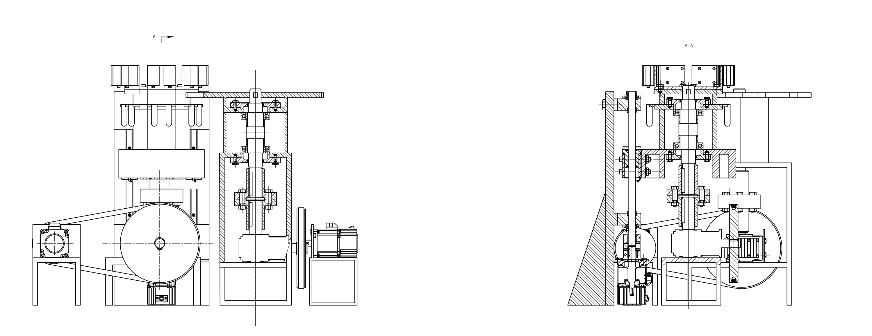
Material-transfer assembly views物料转运系统装配视图
The assembly and sectional views connect the rotary transfer structure with its shafts, supports and drive arrangement.装配与剖面视图联系旋转转运结构、轴系、支承及驱动布置。
Below-platform transmission path台面下方的传动路径
- AC servo交流伺服
- V-belt · i = 2V 带 · i = 2
- Bevel / spur gears · i = 8锥齿轮/直齿轮 · i = 8
- Rotary transfer旋转转运
The bevel stage turns the drive direction within the below-platform layout. A belt ratio of 2 and a gear reduction of 8 give a nominal overall ratio of 16; this ratio describes the design concept, not verified positioning accuracy.锥齿轮级在台面下方的布置中改变传动方向。方案中的 V 带传动比 2 与齿轮减速比 8 对应总传动比 16,用于说明理论传动方案。定位精度尚未验证。
Design Approach设计方法
Mechanical architecture机械传动与执行方案
Rotary drive转盘驱动
I developed the mechanical structure and 3D assembly around an AC servo, a V-belt and a two-stage bevel-and-spur reduction, connecting the below-platform drive to the rotary transfer mechanism.我围绕交流伺服、V 带及锥齿轮—直齿轮二级减速结构,完成机械结构与三维装配设计,将台面下方驱动联系到旋转转运机构。
Vertical positioning升降定位
My engineering calculations and component selection covered the ball screw and linear guides that move the platform. The screw lead, support arrangement and vertical-load calculations still need review before final speed, torque or life figures can be stated.我的工程计算与零部件选型包括平台升降用的滚珠丝杠和直线导轨。丝杠导程、支承方式及垂直载荷计算仍需复核,才能确定最终转速、扭矩和寿命结论。
Pneumatic insertion气动推装
I chose pneumatic insertion as part of the mechanical layout. The original force calculation contains an arithmetic error, so the actual insertion force and effective air pressure must be established before the final cylinder is selected.我在机械布置中采用气动推装方案。原推力计算存在算术问题,最终气缸选型前需要重新确定实际插入力与有效气压。
Selected Preliminary Calculation代表性初步计算
Preliminary V-belt sizingV 带传动初步尺寸设计
Below-platform drive: theoretical design inputs from my own design calculations. Pulley diameters and belt length are assumed to use the same reference system.台面下方传动:输入为本人设计计算中的理论设计值。计算假定带轮直径与带长采用同一基准体系。
Design Inputs设计输入
- Motor power电机功率
- 1 kW
- Application factor工况系数
- 1.2
- Pulley diameters · d / D带轮计算直径 · d / D
- 80 / 160 mm
- Nominal belt length · L名义带长 · L
- 800 mm
- Gear ratio齿轮传动比
- 8
Preliminary Results初步计算结果
- Preliminary design power初步计算功率
- 1.2 kW
- Belt ratioV 带传动比
- 2
- Nominal total ratio名义总传动比
- 16
- Recomputed center distance复算中心距
- ≈ 207.65 mm
Small-pulley wrap小带轮包角 ≈ 157.79°
View Calculation Details展开计算过程
Pd = KA P = 1.2 × 1 = 1.2 kW
ibelt = D/d = 2; itotal = 2 × 8 = 16
L ≈ 2a + π(D + d)/2 + (D − d)²/(4a)
b = L − π(D + d)/2; a = [b + √(b² − 2(D − d)²)]/4
For L = 800 mm, the approximate length equation gives a ≈ 207.65 mm. At the original design estimate of 207.5 mm, the same equation gives L ≈ 799.7 mm; the small difference reflects the approximate center distance used in the original design.带长 L = 800 mm 时,近似长度式得到中心距 a ≈ 207.65 mm。将原设计近似值 207.5 mm 回代,同一公式得到 L ≈ 799.7 mm;这一小幅差异对应原设计采用的近似中心距。
α = 180° − 2 asin[(D − d)/(2a)] ≈ 157.79°
α ≈ 180° − 57.3°(D − d)/a
Tangent geometry gives 157.79° at the recomputed center. The small-angle estimate at 207.5 mm gives 157.9°, consistent with the original design estimate of 157.9°. These values use different approximations.按复算中心距,切线几何包角为 157.79°。在 207.5 mm 中心距下,小角度近似得到 157.9°,对应原设计的 157.9°;两者采用的近似方法不同。
Technical Evidence / Component analysis技术证据 / 零部件分析
Transmission component analysis传动部件分析依据
Theoretical SolidWorks Simulation studies of selected transmission parts. Loads, supports, materials, mesh and strain/displacement units need checking against the original files before strength or stiffness approval.以下为所选传动部件的 SolidWorks Simulation 理论分析。讨论强度或刚度通过结论前,需要用原始文件复核载荷、支承、材料、网格及应变/位移单位。
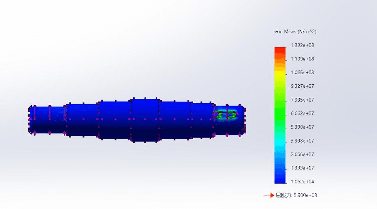
The transfer shaft belongs to the rotary transmission path described above. This plot records my theoretical structural analysis of that component.转运轴对应前文旋转转运的传动路径。此图记录我对该零部件开展的理论结构分析。
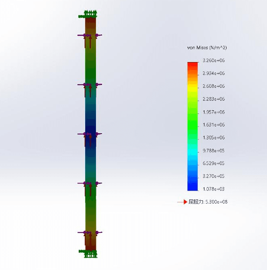
The ball screw belongs to the vertical-positioning arrangement. This plot records my theoretical structural analysis; the screw lead, support and vertical-load assumptions still need review.滚珠丝杠对应平台升降定位机构。此图记录我完成的理论结构分析,丝杠导程、支承及垂直载荷假设仍需复核。
Design records for the adapter-handling subsystem适配器处理子系统的设计成果
The design work produced the mechanical concept and CAD assembly, transmission calculations, component-selection records, part and assembly drawings, and preliminary structural-analysis material for this subsystem.设计工作形成了该子系统的机械方案与 CAD 装配、传动计算、零部件选型记录、零件及装配图,以及初步结构分析资料。